
This chapter describes the methods of bridging supported by the adaptive source routing transparent (ASRT) bridge. Each section gives an overview of a specific technology and is followed by a description of the data frames supported by that technology. The chapter includes the following sections:
The transparent bridge is also commonly known as a spanning tree bridge (STB). The term transparent refers to the fact that the bridge silently forwards non-local traffic to attached LANs in a way that is transparent or unseen to the user. End station applications do not know about the presence of the bridge. The bridge learns about the presence of end stations by listening to traffic passing by. From this listening process it builds a database of end station addresses attached to its LANs.
For each frame it receives, the bridge checks the frame's destination address against the ones in its database. If the frame's destination is an end station on the same LAN, the frame is not forwarded. If the destination is on another LAN, the frame is forwarded. If the destination address is not present in the database, the frame is forwarded to all the LANs that are connected to the bridge except the LAN from which it originated.
All transparent bridges use the spanning tree protocol and algorithm. The spanning tree algorithm produces and maintains a loop-free topology in a bridged network that might contain loops in its physical design. In a mesh topology where more than one bridge is connected between two LANs, looping occurs. In such cases, data packets bounce back and forth between two LANs on parallel bridges. This creates a redundancy in data traffic and produces the phenomenon known as looping.
When looping occurs, you must configure the local and/or remote LAN to remove the physical loop. With spanning tree, a self-configuring algorithm allows a bridge to be added anywhere in the LAN without creating loops. When the new bridge is added, the spanning tree protocol automatically reconfigures all bridges on the LAN into a single loop-free spanning tree.
A spanning tree never has more than one active data route between two end stations, thus eliminating data loops. For each bridge, the algorithm determines which bridge ports can forward data and which ones must be blocked to form a loop-free topology. The features that spanning tree provides include:
During the operation of a router equipped with the spanning tree option, bridge and router software run concurrently. In this mode, the router is a bridge and a router.
During this operation, the following actions occur:
Transparent Bridge implements a spanning tree bridge that conforms to the IEEE 802.1D standard. All transparent bridges (such as Ethernet, FDDI, and Token-Ring) on the network must be 802.1D spanning tree bridges. This spanning tree protocol is not compatible with bridges implementing the proprietary Digital Equipment Corporation spanning tree protocol used in some older bridges.
In a mesh topology where more than one bridge is connected between two LANs, a looping phenomenon can occur where two LANs bounce packets back and forth over parallel bridges. A loop is a condition where multiple data paths exist between two LANs. The spanning tree protocol operating automatically eliminates loops by blocking redundant paths.
During startup, all participating bridges in the network exchange Hello bridge protocol data units (BPDUs) which provide configuration information about each bridge. BPDUs include information such as the bridge ID, root ID, and root path cost. This information helps the bridges to unanimously determine which bridge is the root bridge and which bridges are the designated bridges for LANs to which they are connected.
Of all the information exchanged in the HELLO messages, the following parameters are the most important for computing the spanning tree:
With this information available, the spanning tree begins to determine its shape and direction and then creates a logical path configuration. This process can be summarized as follows:
Through this process, the spanning tree algorithm reduces a bridged LAN network of arbitrary topology into a single spanning tree. With the spanning tree, there is never more than one active data path between any two end stations, thus eliminating data loops. For each bridge on the network, the spanning tree determines which bridge ports to block from forming loops.
This new configuration is bounded by a time factor. If a designated bridge fails or is physically removed, other bridges on the LAN detect the situation when they do not receive Hello BPDUs within the time period set by the bridge maximum age time. This event triggers a new configuration process where another bridge is selected as the designated bridge. A new configuration is also created if the root bridge fails.
When the spanning tree uses its default settings the spanning tree algorithm generally provides acceptable results. The algorithm, however, may sometimes produce a spanning tree with poor network performance. In this case you can adjust the bridge priority, port priority, and path cost to shape the spanning tree to meet your network performance expectations. The following examples explain how this is done.
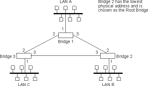
Figure 6 shows three LANs networked using three bridges. Each bridge is using default bridge priority settings for its spanning tree configuration. In this case, the bridge with the lowest physical address is chosen as the root bridge because the bridge priority of each bridge is the same. In this example, this is Bridge 2.
The newly configured spanning tree stays intact due to the repeated
transmissions of Hello BPDUs from the root bridge at a preset interval (bridge
hello time). Through this process, designated bridges are updated with
all configuration information. The designated bridges then regenerate
the information from the Hello BPDUs and distribute it to the LANs for which
they are designated bridges.
Table 3. Spanning Tree Default Values
| Bridge 1 | Bridge 2 | Bridge 3 |
|---|---|---|
| Bridge Priority: 32768 Address: 00:00:90:00:00:10 | Bridge Priority: 32768 Address: 00:00:90:00:00:01 | Bridge Priority: 32768 Address: 00:00:90:00:00:05 |
Port 1
| Port 1
| Port 1
|
Port 2
| Port 2
| Port 2
|
Port 3
| Port 3
| Port 3
|
Figure 6. Networked LANs Before Spanning Tree
 |
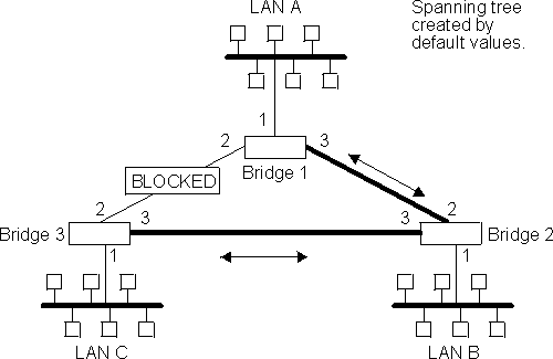
The spanning tree algorithm designates the port connecting Bridge 1 to Bridge 3 (port 2) as a backup port and blocks it from forwarding frames that would cause a loop condition. The spanning tree created by the algorithm using the default values in Table 3 is shown in Figure 7 as the heavy lines connecting Bridge 1 to Bridge 2, and then Bridge 2 to Bridge 3. The root bridge is Bridge 2.
This spanning tree results in poor network performance because the workstations on LAN C can get to the file server on LAN A only indirectly through Bridge 2 rather than using the direct connection between Bridge 1 and Bridge 3.
Figure 7. Spanning Tree Created With Default Values
 |
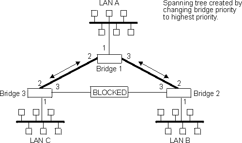
Normally, this network uses the port between Bridge 2 and Bridge 3 infrequently. Therefore you can improve network performance by making Bridge 1 the root bridge of the spanning tree. You can do this by configuring Bridge 1 with the highest priority of 1000. The spanning tree that results from this modification is shown in Figure 8 as the heavy lines connecting Bridge 1 to Bridge 3 and Bridge 1 to Bridge 2. The root bridge is now Bridge 1. The connection between Bridge 2 and Bridge 3 is now blocked and serves as a backup data path.
Figure 8. User-Adjusted Spanning Tree
 |
The 2216 Spanning Tree Bridge protocol provides packet forwarding for the bridging devices in accordance with IEEE Standard 802.1D-1990 Media Access Control (MAC) bridges. The protocol also provides appropriate header translation for Ethernet packets.
An Ethernet/IEEE 802.3 network can simultaneously support the Ethernet data link layer and the IEEE 802.2 data link layer, based on the value of the length/type field in the MAC header. The bridge must translate to and from Ethernet format to provide transparency across mixed LAN types. The algorithm used is based on emerging IEEE standards.
The basic approach consists of translating Ethernet packets to IEEE 802.2 Unnumbered Information (UI) packets using the IEEE 802 SNAP SAP. The SNAP Protocol Identifier has the organization-unique identifier (OUI) of 00-00-00, with the last 2 bytes being the Ethernet type value.
Some IBM personal computers (IBM RT PC running AIX or any PC running OS/2 EE) encapsulate SNA within Ethernet Type 2 packets instead of using IEEE 802.3 Ethernet encapsulation. This requires a special Ethertype header that contains the length of the MAC user data followed by the IEEE 802.2 (LLC) header.
The processing of these frames can be enabled/disabled on a per-port basis. In the enabled mode, the bridge learns the source station's behavior. When frames are targeted for such stations, the bridge generates the correct frame format. If there is no information about the station's behavior, (as with multicast or unknown stations), the bridge produces duplicate frames, one in IEEE 802.3 and IEEE 802.2 format, and the other with the IBM-RT header.
XNS Ethernet frames use Ethertype 0x0600. When translated to token-ring format, these frames get SNAP as specified in IEEE 802.1H. Because some Token-Ring end stations use the Ungermann-Bass OUI in the SNAP for such frames, there is a configuration switch to activate this encapsulation. The switch to activate this encapsulation is set with the frame token_ring_SNAP command.
The Frame Relay interface forwards transparent frames from Ethernet, FDDI, and Token-Ring networks, provided that bridging is enabled on the circuit. IP tunneling does not have to be used.
Hello BPDUs are generated and transmitted for each circuit configured for transparent bridging. The spanning tree protocol causes Frame Relay circuits that have not been designated as part of the active data path to be BLOCKED, thereby eliminating loops.
The ATM interface forwards transparent frames from Ethernet, FDDI, and Token-Ring networks, provided bridging is enabled on the virtual channel connection (VCC). IP tunneling does not have to be used.
Hello BPDUs are generated and transmitted for each VCC configured for transparent bridging. The spanning tree protocol causes ATM VCCs that have not been designated as part of the active data path to be BLOCKED, thereby eliminating loops.
The 10/100 Ethernet and FDDI adapter hardware provide transparent bridge filtering of local LAN packets to offload the bridging software. The filter is initialized and enabled when the adapter is activated and functions as follows:
This section reviews the terms and concepts commonly used in transparent bridging.
The length of time (age) before a dynamic entry is removed from the filtering database when the port with the entry is in the forwarding state. If dynamic entries are not referenced by the aging time, they are deleted.
A protocol-independent device that connects local area networks (LANs). These devices operate at the data link layer, storing and forwarding data packets between LANs.
The least significant 6-octet part of the bridge identifier used by the spanning tree algorithm to identify a bridge on the network. The bridge address is set to the MAC address of the lowest-numbered port by default. You can override the default address by using the set bridge configuration command.
The bridge hello time specifies how often a bridge sends out Hello BPDUs (containing bridge configuration information) when it becomes the root bridge in the spanning tree. This value is useful only for the root bridge because it controls the hello time for all bridges in the spanning tree. Use the set protocol bridge command to set the bridge hello time.
The amount of time a bridge port spends in the listening state as well as the learning state. The forward delay is the amount of time the bridge port listens in order to adjust the spanning tree topology. It is also the amount of time the bridge spends learning the source address of every packet that it receives while the spanning tree is configuring. This value is useful only for the root bridge because it controls the forward delay for all bridges in the spanning tree.
The root bridge conveys this value to all bridges. This time is set with the set protocol bridge command. The procedure for setting this parameter is discussed in the next chapter.
A unique identifier that the spanning tree algorithm uses to determine the spanning tree. Each bridge in the network must have a unique bridge identifier.
The bridge identifier consists of two parts: a least-significant 6-octet bridge address and a most-significant 2-octet bridge priority. By default, the bridge address is set to the MAC address of the lowest-numbered port. You can override the default address with the set bridge configuration command.
The amount of time that spanning tree protocol information is considered valid before the protocol discards the information and a topology changes. All the bridges in the spanning tree use this age to time out the received configuration information in their databases. This can cause a uniform timeout for every bridge in the spanning tree. Use the set protocol bridge command to set the bridge maximum age.
The most significant 2-octet part of the bridge identifier set by the set protocol bridge command. This value indicates the chances of each bridge becoming the root bridge of the network. In setting the bridge priority, the spanning tree algorithm chooses the bridge with the highest priority value to be the root bridge of the spanning tree. A bridge with the lowest numerical value has the highest priority value.
The bridge that claims to be the closest to the root bridge on a specific LAN. This closeness is measured according to the accumulated path cost to the root bridge.
The port ID of the designated bridge attached to the LAN.
Databases that contain information about station addresses that belong to specific port numbers of ports connected to the LAN.
The filtering database is initialized with entries from the permanent database. These entries are permanent and survive power on/off or system resets. You can add or delete these entries through the spanning tree configuration commands. Entries in the permanent database are stored as static random access memory (SRAM) records, and the number of entries is limited by the size of SRAM.
| Note: | You can also add entries (static) by using the monitoring commands but these do not survive power on/off and system resets. |
The filtering database also accumulates entries learned by the bridge (dynamic entries) which have an aging time associated with them. When entries are not referenced over a certain time period (age time), they are deleted. Static entries are ageless, so dynamic entries cannot overwrite them.
Entries in the filtering and permanent databases contain the following information:
Make changes to the permanent database through the spanning tree configuration commands and make changes to the filtering database through the GWCON monitoring process.
Two or more bridges connecting the same LANs.
Each port interface has an associated path cost which is the relative value of using this port to reach the root bridge in a bridged network. The spanning tree algorithm uses the path cost to compute a path that minimizes the cost from the root bridge to all other bridges in the network topology. The sum total of all the designated costs and the path cost of the root port is called the root path cost.
The bridge's connection to each attached LAN or WAN. A bridge must have at least two ports to function as a bridge.
A 2-octet port identifier. The most-significant octet represents the port priority and the least-significant octet represents the port number. Both port number and port priority are user-assignable. The port ID must be unique within the bridge.
A user-assigned 1-octet part of the port ID whose value represents the attachment to the physical medium. A port number of zero is not allowed.
The second 1-octet part of the port ID. This value represents the priority of the port that the spanning tree algorithm uses in making comparisons for port selection and blocking decisions.
The time factor by which dynamic entries are ticked down as they age within the database. The range is 1 to 60 seconds.
The bridge selected as the root of the spanning tree because it possesses the highest priority bridge ID. This bridge is responsible for keeping the spanning tree intact by regularly emitting Hello BPDUs (containing bridge configuration information). The root bridge is the designated bridge for all the LANs to which it is connected.
The port ID of a bridge's port that offers the lowest cost path to the root bridge.
A topology of bridges such that there is one and only one data route between any two end stations.
This type of bridging involves a mechanism that is transparent to end stations applications. Transparent bridging interconnects local area network segments by bridges designated to forward data frames through a spanning tree algorithm.
Source routing is a method of forwarding frames through a bridged network in which the source station identifies the route that the frame will follow. In a distributed routing scheme, routing tables at each bridge determine the path that data takes through the network. By contrast, in a source routing scheme, the source station defines the entire route in the transmitted frame.
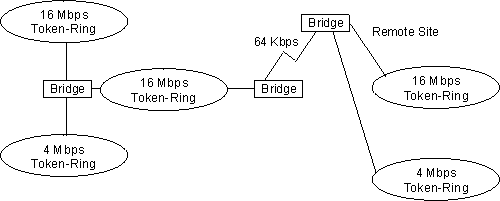
The source routing bridge (SRB) provides local bridging over 4 and 16 Mbps token-rings, as shown in Figure 9. It can also connect remote LANs through a telecommunications link operating at speeds up to E1.
Figure 9. Example of Source Routing Bridge Connectivity
 |
Among its features, the source routing bridge provides:
Source routing end stations see this path as a single hop, regardless of the network complexity. This helps overcome the usual seven-hop distance limit encountered in source routing configurations. This feature also lets you connect source routing end stations across non-source routing media (for example, Ethernet networks).
As mentioned, the source station defines the entire route in the transmitted frame in a source routing configuration. The source routing bridge is dynamic. Both end stations and bridges participate in the route discovery and forwarding process. The following steps describe this process:
As the route discovery frame continues its search for the destination end station, each bridge that forwards it adds its own bridge number and segment number to the routing information field (RIF) in the frame. As the frame continues to pass through the bridged network, the RIF compiles a list of bridge and segment number pairs describing the path to the destination.
When the broadcast frame finally reaches its destination, it contains the exact sequence of addresses from source to destination.
As mentioned, bridges interconnect LANs by relaying data frames, specifically MAC frames, between the separate MAC entities of the bridged LANs. MAC frames provide the necessary "Where?" information in the form of source and destination addresses. This information is essential for the successful transmission and reception of data.
In source routing, the data frame forwarding decision is based on routing information within the frame. Before the frame is forwarded, end stations have obtained the route to the destination station by the route discovery process. The source station that originates the frame designates the route that the frame will travel by imbedding a description of the route in the routing-information field (RIF) of the transmitted frame. A closer look at the various types of source routing bridge frames will help to further explain how the bridge obtains and transmits this routing information.
Because source routing MAC frames contain routing information necessary for data communication over multi-ring environments, they differ slightly in format from the typical token-ring MAC frames. The presence of a "1" in the RII within the source address field indicates that a RIF containing routing information follows the source address. Figure 10 provides a closer look at the format of the source address field of a source routing frame.
Figure 10. 802.5 Source Address Format
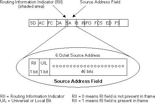 |
When the RII in the source address field is set to 1, a RIF is present after the source address. The RIF is required because it provides route information during source routing. It consists of a 2-octet routing control (RC) field and a series of 2-octet route designator (RD) fields. Figure 11 provides a closer look at the format of the Routing Information Field.
Figure 11. 802.5 Routing Information Field
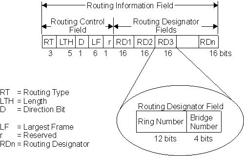 |
The following information describes each field in the RIF:
Indicates by bit settings if the frame is to be forwarded through the network along a specific route or along a route (or routes) that reaches all interconnected LANs. Depending on the bit settings in this field, the source routing frame can be identified as one of the following types:
All-paths explorer frames exist if the RT bits are set to 100. These frames are generated and routed along every non-repeating route in the network (from source to destination). This process results in as many frames arriving at the destination end station as there are different routes from the source end station. This routing type is the response to receiving a route discovery frame sent along the spanning tree to the present originating station using all the routes available. The forwarding bridges add routing designators to the frame.
A spanning tree explorer frame exists if the RT bits are set to 110. Only spanning tree bridges relay the frame from one network to another. This means that the frame appears only once on every ring in the network and therefore only once at the destination end station. A station initiating the route discovery process uses this frame type. The bridge adds routing designator fields to the frame. It can also be used for frames sent to stations using a group address, which is discussed more fully in the next section.
Specifically routed frames exist if the first RT bit is set to 0. When this is the case, the Route Designator (RD) fields containing specific routing information guide the frame through the network to the destination address. Once the frame reaches its destination and discovers a route path, the destination station returns a specifically routed frame (SRF) to the source station. The source station then transmits its data in a specifically routed frame.
If necessary, the destination station further reduces the LF value to indicate its maximum frame capacity.
LF bit encoding is made up of a 3-bit base encoding and a 3-bit extended encoding (6 bits total). The SRT bridge (explained in a later section) contains an LF mode indicator that enables the bridge to select either base or extended LF bits. When the LF mode indicator is set to the base mode, the bridge sets the LF bits in explorer frames with the largest frame base values. When the LF mode indicator is set to extended mode, the bridge sets the LF bits in explorer frames with the largest frame extended values.
The spanning tree explore feature lets you select a single route to a destination when your network has two or more bridges connecting the same LANs. With this feature enabled, only the bridges you select receive spanning tree explorer (STE) frames. Not to be confused with the spanning tree protocol, this option enables you to:
A spanning tree network contains a single data route between any two end stations. If your network uses two or more parallel bridges, such as those in Figure 12, you can manually configure a spanning tree in a network by preventing duplication of discovery frames onto the network. Without spanning tree explore enabled, if Station Q transmits a discovery frame to a Station R, both Bridge A and Bridge B retransmit that frame. Segment 2 then receives two copies of the same frame.
With spanning tree explore enabled, each LAN segment on the network receives only one copy of the transmitted frame. Only the bridges you select can receive STE frames, reducing the creation of redundant frames and lowering network overhead.
Figure 12. Example of Parallel Bridges
 |
You can also use the spanning tree explore option for load balancing. For example, in Figure 13, Bridge A is configured to accept STE frames over the interface connecting Segment 2. Bridge B is configured to accept STE frames over the interface connecting Segment 1. Traffic travels in the direction of the arrows. This configuration enables parallel bridges to share the traffic load.
Figure 13. Using Spanning Tree Explore for Load Balancing
 |
| Note: | For source routing to work, some end-node applications such as the IBM PC LAN program require you to enable spanning tree explore on attached interfaces. For parallel bridge configuration, the spanning tree explore option should be enabled only on one of the parallel interfaces. However no serious harm (other than some extra traffic) results from having too many interfaces enabled for the spanning tree. |
If you use the spanning tree explore option and any bridge on the single-route path goes down, source routing traffic cannot reach its destination. You must manually reconfigure an alternate path.
If source routing bridging is enabled, source-routed frames are forwarded between the Frame Relay interface and the bridging forwarder. You can configure the bridge to treat each Frame Relay virtual circuit as a bridge port with a unique ring number. Additionally, Frame Relay virtual circuits that are not configured as bridge ports can be grouped together as a single multiaccess bridge port with a unique ring number. For more information, see Understanding Multiaccess Bridge Ports. Some virtual circuits that are not part of the active data path are BLOCKED in order to maintain the loop-free topology.
If source routing bridging is enabled on the virtual channel connection (VCC), source-routed frames are forwarded between the ATM interface and the bridging forwarder. A unique destination ring number is configured for each VCC. Some VCCs that are not part of the active data path are BLOCKED in order to maintain the loop-free topology.
This section reviews the terms and concepts commonly used in source routing bridging.
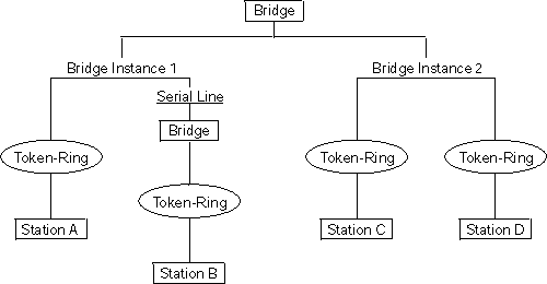
The bridge instance identifies the sequence of a bridge defined in the software. For example, in a bridge with two configured bridges, the bridge instances would be 1 and 2.
Bridge instances within a single bridge are independent and do not communicate. For example, in Figure 14, Station A cannot pass data to either station on Bridge Instance 2. It can pass frames only to Station B. In effect, the bridge instance enables you to create two separate networks. These networks do not communicate unless they physically interconnect at some other point.
Figure 14. Bridge Instances within a Bridge
 |
The bridge number is a 4-bit hexadecimal value that identifies a bridge. Although bridges which are attached to the same ring can have the same bridge number, parallel bridges (bridges that are connected to the same two rings) must have unique bridge numbers.
The source routing bridge adds routing information to an explorer frame as it forwards the frame through the network to its destination end station. The explorer frame is used to discover routes. There are two types of explorer frames: all-routes explorer (ARE) frames and spanning-tree explorer (STE) frames. ARE frames are forwarded by all ports while STE frames are forwarded only by ports assigned to forward them by the spanning tree protocol.
The interface number identifies a "physical" interface within the hardware/product and must be tied to the "logical" interface that is understood by a bridge (that is a port). When you configure the device software, the router/bridge numbers the ports sequentially. To use the source routing bridge, you must use the port numbers to identify the interface that connects each network segment.
The route is a path through a series of LANs and bridges for example, SRB bridges.
Route discovery is the process by which a route is learned to a destination end station.
The segment number identifies each individual LAN, such as a single token-ring or serial line. A segment connects to the bridge, but can also operate independently.
Source routing is a bridging mechanism that routes frames through a multi-LAN network by specifying in the frame the route it will travel.
Having worked hard to adopt standardized technologies (Ethernet and token-ring are both defined by IEEE), you may actually be forced back into the proprietary arena when trying to connect them. This is because bridges function differently in token-ring and Ethernet networks.
Aside from the differences such as bit-ordering, packet size, and acknowledgment bits, differences in bridging methods are another obstacle. Ethernet bridges use the transparent bridging method in which the bridges determine the route of the traffic through the network. Token-ring networks use transparent bridging only in some instances, so they generally depend on source routing as the primary bridging method. FDDI for 2216 supports only transparent bridging.
Source routing cannot operate in a transparent environment because transparent packets contain no routing information. In this case, the bridge has no way of knowing whether to forward the packet. While transparent bridging can operate in a source routing environment, it does so without any routing information being passed to an end station. Significant information (for example, packet sizing) is missing and can potentially create problems.
IEEE has ratified an extension to the 802.1D transparent bridging standard called source routing transparent (SRT). SRT is a bridging technology that attempts to resolve a large part of the incompatibility inherent in bridging token-ring and Ethernet/FDDI. It saves you the cost of installing multiple bridges and separate links to support the two types of traffic by adding a parallel bridging architecture (rather than an alternative) to the transparent bridging standard.
A source routing transparent (SRT) bridge is a MAC bridge that performs source routing when source routing frames with routing information are received and that performs transparent bridging when frames are received without routing information. In SRT, all the bridges between Ethernets/FDDI and token-rings are transparent. The bridges operate at the MAC sublayer of the data link layer and are completely invisible to the end stations.
The SRT bridge distinguishes between the two types of frames by checking the value in the RII field of the frame (see "Source Routing Frames" for more information). An RII value of 1 indicates that the frame is carrying routing information while a value of 0 in the RII indicates that no routing information is present. With this method, the SRT bridge forwards transparent bridging frames without any conversions to the outgoing media (including token-ring). Source routing frames are restricted to the source routing bridging domain.
The spanning tree protocol and algorithm forms a single tree involving all the networks connected by SRT bridges. The SRT-bridged network offers a larger domain of transparent bridging with sub-domain of source routing. Thus, transparent frames are capable of reaching to the farthest side of the SRT- and TB-bridged LAN while source routed frames are limited to only the SRT- and SRB- bridged LAN. In the SRT bridging model, source routing and transparent bridging parts use the same spanning tree. In the SRT-bridged domain, end stations are responsible for answering the "Source Routing or Transparent Bridging" question.
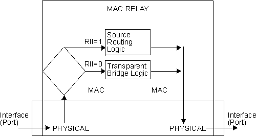
With an SRT bridge, each bridge port receives and transmits frames to and from the attached local area networks using the MAC services provided by the individual MAC entity associated with that port. The MAC relay entity takes care of the MAC-independent task of relaying frames between bridge ports. If the received frame is not source-routed (RII = 0), then the bridge frame is forwarded or discarded using the transparent bridging logic. If the received frame is source-routed (RII = 1), then the frame is handled according to the source routing logic. This process is illustrated in Figure 15. The arrows represent the data path.
Figure 15. SRT Bridge Operation
 |
SRT differentiates between source-routed and non-source-routed traffic on a frame-by-frame basis. If the packet is source-routed, the bridge forwards it as such. If it is a transparent bridge packet, the bridge determines the destination address and forwards the packet.
If SRT bridging is enabled on the circuit, source routed and transparent frames are forwarded between the Frame Relay interface and the bridging forwarder.
If SRT bridging is enabled on the virtual channel connection (VCC), source routed and transparent frames are forwarded between the ATM interface and the bridging forwarder.
This section reviews the terms and concepts commonly used in SRT bridging.
The source routing bridge adds routing information to an explorer frame as it forwards the frame through the network to its destination end station. The explorer frame discovers routes. There are two types of explorer frames:
ARE frames are intended to be forwarded by all ports while STE frames are forwarded only by ports assigned to forward them by the spanning tree protocol.
In source routing, the data frame forwarding decision is based on routing information within the frame. Before forwarding the frame, end stations obtain the route to the destination station by the route discovery process. The station that originates the frame (that is, the source station) designates the route that the frame will travel by imbedding a description of the route in the Routing Information Field (RIF) of the transmitted frame.
Because source routing MAC frames contain routing information necessary for data communication over multi-ring environments, their format differs slightly from the typical token-ring MAC frames. The presence of a 1 in the source address field called the Routing Information Indicator indicates that a Routing Information Field containing routing information follows the source address. The SRT bridge distinguishes between source-routed and non-source-routed frames by checking for a 1 or 0 value in the RII field.
A bridging mechanism that routes frames through a multi-LAN network by specifying in the frame the route it will travel.
A topology of bridges in which there is only one data route between any two end stations.
A type of bridging that involves a mechanism that is transparent to end stations. Transparent bridging interconnects local area network segments by bridges designated to forward data frames through in a spanning tree algorithm.
The adaptive source routing transparent (ASRT) bridge is a software collection of several bridging options. The ASRT bridge software combines transparent bridging and source routing so that they function separately or can be combined as a single ASRT bridge. This extended function enables communication between a strict source routing end station and a transparent end station via an ASRT bridge. Depending on the set of configuration commands used, the ASRT bridge provides the following bridging options:
The ASRT bridge is modeled after the source routing transparent bridge described in IEEE 802.5M/Draft 6 (1991) of SRT. Modifications have been built into the ASRT bridge which provide users with extended function that goes beyond compliance with the SRT standard. The ASRT bridge allows compatibility with the installed base of source routing bridges, while still enabling them to link Ethernet, FDDI, and token-ring LANs. ASRT also enhances basic SRT function in some additional, critical ways described in the following sections.
While source routing is still available in the SRT model, it is available only between adjacent source routing token-rings. Source routing-only bridges cannot coexist with SRT bridges that link Ethernet/FDDI and token-ring LANs. Because a token-ring end node needs to communicate with an Ethernet/FDDI node, it must be configured to omit RIFs. Also, if the end node is configured to omit RIFs, it cannot communicate through ordinary source routing bridges that require that RIF.
The source routing - transparent bridge (SR-TB) option interconnects networks using source routing bridging (source routing domain) and transparent bridging (transparent bridging domain). It transparently joins both domains. During operation, stations in both domains are not aware of the existence of each other or of the SR-TB bridge. From a station's point of view, any station on the combined network appears to be in its own domain.
The bridge achieves this function by converting frames from the transparent bridging domain to source routing frames before forwarding them to the source routing domain (and conversely). This is accomplished by the bridge maintaining a database of end-station addresses each with its Routing Information Field in the source routing domain. The bridge also conducts route discovery on behalf of the end stations present in the transparent bridging domain. The route discovery process is used to find the route to the destination station in the source routing domain. Frames sent to an unknown destination are sent in the spanning tree explorer (STE) format.
The SR-TB bridge anticipates three types of spanning trees:
The following sections discuss the operation of the SR-TB bridge in more detail.
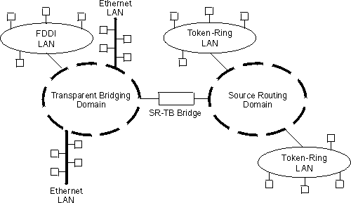
During SR-TB operation, a network is partitioned into a series of two or more separate domains. Each domain is made up of a collection of LAN segments interconnected by bridges all operating under a common bridging method. This can create networks comprised of two types of domains (depending upon the bridging method):
Figure 16 shows an example of these domains. With separate domains, each source routing domain has a single-route broadcast topology set up for its bridges. Only bridges belonging to that source routing spanning tree are designated to forward single-route broadcast frames. In this case, frames that carry the single-route broadcast indicator are routed to every segment of the source routing domain. Only one copy of the frame reaches each segment because the source routing spanning tree does not allow multiple paths between any two stations in the domain.
Figure 16. SR-TB Bridge Connecting Two Domains
 |
The SR-TB bridge is a two-port device with a MAC interface assigned to the LAN segment on the source routing side and another assigned to the LAN segment on the transparent bridging side. Each end station reads the appropriate MAC layer for its LAN segment. This means that bridging functions can be divided into two types of operations:
On the transparent bridging side, the SR-TB bridge operates the same as any other transparent bridge. The bridge keeps a table of addresses for stations it knows are transparent bridging stations. The SR-TB bridge observes the inter-bridge protocols necessary to create and maintain the network spanning tree because more than one SR-TB bridge joins different domains.
The SR-TB bridge forwards the frames received from its transparent bridging station to the source routing side of the bridge only if the destination address carried in the frame is not found in the bridge's transparent bridging side address table.
On the source routing bridging side, the SR-TB bridge combines the functions of a source routing bridge and a source routing end station in a specific way. As a source routing end station, the bridge maintains an association of destination addresses and routing information on the source routing side. It communicates either as an end station for applications in the bridge itself (for example, network management) or as an intermediary for stations on the transparent bridging side.
The SR-TB bridge forwards the frames received from its transparent bridging station to the source routing side of the bridge only if the destination address carried in the frame is not found in the bridge's transparent bridging side address table. Frames transmitted by the bridge's source routing station carry the routing information associated with the bridge, if such information is known and held by the bridge.
As a source routing bridge, the SR-TB bridge participates in the route discovery process and in the routing of frames already carrying routing information. The route designator unique to the SR-TB bridge consists of the LAN number of the individual LAN on its source routing side and the bridge's individual bridge number.
The bridge also maintains a single LAN number representing all of the LANs
on the transparent bridging side. The SR-TB bridge treats each case of
received and forwarded frames differently as described in Table 4.
Table 4. SR-TB Bridge Decision Table
| Type of Frame Received | Action Taken by SR-TB Bridge |
|---|---|
| Non-routed frames received by the source routing station. | Does not copy or forward frames carrying routing information. |
| All-routes broadcast frame received by the source routing station. | Copies frame and sets A and C bits of the broadcast indicator in the repeated frame. If the destination address is in the transparent bridging table, the bridge forwards the frame without routing information on the transparent bridging network. Otherwise, the frame is not forwarded. |
| Single-route broadcast frame received by the source routing station. The bridge is not designated as single-route broadcast bridge. | Does not copy or forward the frame. |
| Single-route broadcast frame received by the source routing station. The bridge is designated as single-route broadcast bridge. | Copies frame, sets A and C bits in the broadcast indicator, removes the routing information from the frame, and forwards the modified frame to transparent bridging side. Adds its bridge number to the saved routing information field and the LAN number for transparent bridging side. Changes the broadcast indicator to non-broadcast, complements D-bit, and stores this routing information for the source address of the frame. |
| Non-broadcast frame received by the source routing station. | If frame carries specific route, bridge examines the routing information. If SR-TB bridge is part of the route and appears between the LAN number for the source routing side and LAN number for transparent bridge side, the bridge copies the frame and sets A and C bits in the repeated frame. Forwards frame to the transparent bridging side without routing information. If bridge does not already have a permanent route for the source address, it saves a copy of the routing information, complements D-bit, and stores saved routing information for the source address of the frame. |
| Frame received from the transparent bridging side. | To forward frame to the source routing side, the bridge first determines if it has routing information associated with the destination address carried in the frame. If yes, the bridge adds routing information to the frame, sets the RII to 1, and queues the frame for transmission on the source routing side. If no, the bridge adds a routing control field to the frame containing an indicator for single-route broadcast and two route designators containing the first two LAN numbers and its own individual bridge number. |
The SR-TB bridge interconnects source routing domains with transparent bridging domains by transparently joining the domains. During operation, stations in both domains are unaware of the existence of each other or of the SR-TB bridge. From the end station's point of view, any station on the combined network appears to be in its own domain.
The following sections provide specific examples of frame forwarding during SR-TB bridging. These examples assume that the SR-TB bridge is designated as a single-route broadcast bridge. Figure 17 provides the following information to accompany the situations described in each section:
Figure 17. SR-TB Bridging Examples
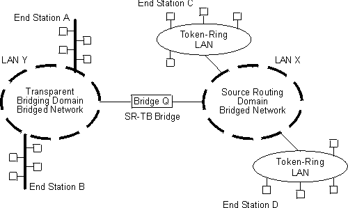 |
When the SR-TB bridge receives a frame with a source address of end station A and a destination address of end station B, it enters end station A's address into its transparent bridging side address table. This table contains the addresses of stations known to be on the transparent bridging side of the bridge, which is the normal process for transparent bridging.
If end station B's address is in the transparent bridging side's address table, the SR-TB bridge does not forward the frame. If end station B's address is not in the transparent bridging side's address table and not in the source routing side's address table, its location is not known to the SR-TB bridge. In this case, the frame is forwarded on the source routing side as a single-route broadcast with no request for route explorer return. Any frame sent by end station B (regardless of its destination) causes its address to be added to the transparent bridging address table. This prevents future forwarding of frames addressed to end station B to the source routing side.
In this example, end station A's address is treated the same as the previous example. Because end station C's address will definitely not be in the transparent bridge address table, the SR-TB bridge will forward the frame on the source routing side.
The bridge then looks for end station C's address in its source routing address table. This table contains all known addresses with related routing information for stations known to be on the source routing side of the bridge. If C's address is in the source routing table, the bridge forwards the frame using the routing information in the address table. If C's address is not in the source routing table (or if it appears but has null routing information), the bridge forwards the frame on the source routing side as a single-route broadcast with no request for route explorer return.
When end station C receives this frame, it enters end station A's address in its source routing table together with the reverse direction of the route built from the SR-TB bridge and marks it as a temporary entry. When end station C later tries to send a frame to end station A, it will use this specific route, and because the route is marked as temporary, the frame will be sent as a non-broadcast route with a request for route explorer return.
When the returning frame arrives at the SR-TB bridge, it is forwarded on the transparent bridge side without routing information but will cause the route to end station C to be entered in the source routing table as a temporary route. This further causes the network management entity to send a route-explorer frame with an all-routes broadcast setting back to end station C. This lets end station C select the optimal routing for frames addressed to end station A to be entered as a permanent route in the SR-TB bridge's source routing table.
If the frame is sent as a non-broadcast and crosses over the segment to which the SR-TB bridge is attached, the bridge scans the RII field for the routing sequence (LAN X to Bridge Q to LAN Y). It cannot find the sequence and so will not forward the frame.
If the frame is sent as a single-route broadcast, the bridge will discard the frame if end station D is already known to be on the source routing side. If end station D is not known to be on the source routing side, the bridge forwards the frame to the transparent bridging side (minus the routing information), and adds "Q to Y" to the routing information. Finally, it saves the routing information for end station C as a temporary route in the source routing table with a non-broadcast indicator and the direction bit complemented.
If the frame is sent as an all-routes broadcast, the SR-TB bridge discards the frame (because end station D's address is not present in the transparent bridging address table) and makes sure that end station C's address is in the source routing table.
If the frame is sent non-broadcast, the bridge scans the RII field for the routing sequence (X to Q to Y). When it finds it, it forwards the frame to the transparent bridging side. It also stores the routing information for end station C.
If the frame is sent as a single-route broadcast, the bridge forwards the frame (minus the routing information) to the transparent bridging side and adds "Q to Y" to the routing information. It also sets the non-broadcast indicator, complements the direction bit, and enters the routing information for C's address in its source routing table.
If a temporary entry for end station C already exists in the source routing table, the SR-TB bridge updates the routing information. If the frame is sent as an all-routes broadcast, the bridge discards the frame but makes sure that end station C's address is in the source routing table.
The Frame Relay interface supports SR-TB bridging by forwarding all bridged frames to the appropriate bridging forwarder as long as bridging has been enabled on the circuit.
The ATM interface supports SR-TB bridging by forwarding all bridged frames to the appropriate bridging forwarder as long as bridging has been enabled on the VCC.
This section describes the terms and concepts used in SR-TB bridging.
The process of sending a frame through every non-repeating route in the bridged LAN.
The process of addressing a frame (placing all ones in the destination address) so that every station on the ring the frame appears on copies the frame.
A protocol-independent device that connects local area networks (LAN). Bridges operate at the data link layer, storing and forwarding data packets between LANs.
The unique number identifying a bridge. It distinguishes between multiple bridges connecting the same two rings.
The source routing bridge adds routing information to an explorer frame as it forwards the frame through the network to its destination end station. The explorer frame discovers routes. There are two types of explorer frames: all-routes explorer (ARE) frames and spanning-tree explorer (STE) frames. ARE frames are forwarded by all ports while STE frames are forwarded only by ports assigned to forward them by the spanning tree protocol.
The unique number identifying a ring in a bridged network.
A path through a series of LANs and bridges (for example, source routing bridges).
A ring number and a bridge number in the Routing Information Field used to build a route through the network.
The process of learning a route to a destination end station.
A number that identifies each individual LAN, such as a single token-ring or serial line. A segment connects to the bridge, but can also operate independently.
The process of sending a frame through a network such that exactly one copy of the frame appears on each ring in the network.
A bridging mechanism that routes frames through a multi-LAN network by specifying in the frame the route it will travel.
A topology of bridges such that there is only one data route between any two end stations.
A type of bridging that involves a mechanism that is transparent to end station applications. Transparent bridging interconnects local area network segments by bridges designated to forward data frames in a spanning tree algorithm.
First, the ASRT bridge provides transparent bridge compatibility with ordinary source routing bridges through source routing bridge conversion (SR-TB). SR-TB was originally proposed as part of the 802.5 specification. This implementation is similar to and can interoperate with IBM's 8209 conversion bridge.
SR-TB converts transparent bridging frames to source routing frames and conversely. In other words, instead of just checking to see whether an RIF is present in a packet and forwarding it to a like destination, the ASRT bridge can translate the packet into either format; it functions as either a transparent bridge or a source routing bridge by inserting or removing an RIF as necessary. With this function, packets can move between Ethernet/FDDI and SRT token-ring LANs and still be compatible with an installed base of source routing token-ring LANs.
SR-TB also eliminates packet sizing problems in token rings being bridged together across an Ethernet domain. In this configuration, end stations use the source routing protocol, which enables them to dynamically determine that there is a network with a 1518-byte maximum frame size between them. The end station automatically honors this limit without a manual reconfiguration. In the reverse situation, bridging Ethernets across a token-ring domain, packet size is not a problem because the token-ring packet size allowance is much larger.
Another key feature provided by the ASRT bridge is hardware address filtering. Hardware address filtering solves the conflict in packet acknowledgment methods that exists in the Ethernet and token-ring LAN technologies. It occurs in the MAC layer and is the only technique that accurately sets acknowledgment bits based on the destination MAC address. The ASRT bridge uses content-addressable memories (CAMs) to implement hardware address filtering. This technology effectively gives the bridge a higher level of intelligence by providing instantaneous lookup of MAC addresses without creating any performance penalty.
Because bridges are continually being built to connect LANs with different MAC address types, bit ordering during data transmission affects the inter-operability of these technologies.
In administering MAC addresses, IEEE assigns addresses known as 48-bit IEEE globally assigned unique MAC addresses. These addresses are supported by FDDI, 802.3, 802.4, and 802.5 LANs. Due to the lack of standards at the time this addressing scheme was developed, two different situations have arisen:
| Note: | For simplicity, 802.3 and 802.4 bridges and LANs will now be referred to as LSB bridges and LANs. FDDI, 802.5 bridges and LANs will be referred to as MSB bridges and LANs. |
The difference in the bit transmission standard means that a bridge from LSB to MSB LANs has to reverse the bit order of the destination and source MAC addresses at the start of the MAC frame. This is because the different LAN types use the same bit order for the MAC address (that is, group bit first) and yet use a different bit order for the user data (either LSB or MSB first).
The misinterpretation of addresses due to reversed bit ordering is compounded by the fact that some of the higher level communication protocols misinterpret MAC addresses altogether. Protocols such as IP and Novell IPX interpret bridging addresses incorrectly because at the time of their initial development, there was no standard representation of MAC addresses.
The bit order differential is best resolved by combining bridging technology (data link layer technology) with routing technology (network layer technology). Rather than ask the user to "reverse engineer" today's communications protocols and configure each bridge to "flip" or reverse addresses on a case-by-case basis, the problem is more easily solved by routing these protocols.
Routing eliminates the bit order and protocol addressing problems by accessing the detailed packet addresses running at the higher layer. Routing alone is not a complete solution, because other protocols such as IBM Frames and NetBIOS cannot be routed, and SNA routing is limited. Therefore, it is important to implement SRT in a device where bridging and routing work hand-in-hand.
The ASRT bridge uses the spanning tree protocol and algorithm described in the IEEE 802.1D bridge standard over all interfaces. It is possible that more than one spanning tree will form in an environment where different types of bridges exist. For example a spanning tree of all bridges practicing IEEE 802.1d protocol (for example, STB and SRT) existing with another tree of IBM 8209 bridges. The loops forming from this configuration require you to correct the situation.
TCP/IP Host Services support SDLC relay. When running as a pure bridge, and not as an IP router, functions usually associated with an IP router are not available. For example, there is no BootP forwarder function or any ARP subnet routing capabilities.
With an ASRT bridge, the collection of configuration parameters for the
bridge and all connected interfaces produces a bridge personality
for that bridge. The following matrix provides a guide to the
configuration settings needed for each interface type to produce the desired
bridge personality to handle your network.
| Bridge Personality | SR <-> TB Conversion Enabled? | Interface Type & Bridging Method Setting | |||
|---|---|---|---|---|---|
| Token Ring | FDDI or Ethernet | Serial Line or Tunnel | ATM | ||
| STB | No | TB | TB | TB | TB |
| SRB | No | SR | -- | SR | SR |
| STB & SRB | No | SR | TB | TB or SR | TB or SR |
| SR-TB | Yes | SR | TB | TB | TB |
| SR-TB | Yes | SR | TB | SR | SR |
| SRT | No | SR & TB | TB | SR & TB | SR & TB |
| ASRT | Yes | SR & TB | TB | SR & TB | SR & TB |
| ASRT | Yes | SR | TB | SR & TB | SR & TB |
| ASRT | Yes | SR or TB | TB | SR & TB | SR & TB |
| Bridge Personality Key:
Bridging Method Key: SR = Source Routing TB = Transparent Bridging | |||||